In the realm of wireless communication, antennas play a crucial role in transmitting and receiving signals. For professionals working in telecommunications or enthusiasts setting up their radio systems, understanding antenna patterns and their corresponding received power levels—a term referred to as ‘Rx Power’—is essential. This guide is designed to help you demystify the process of calculating Rx Power from an antenna pattern. Whether for optimising signal strength or troubleshooting communication systems, mastering this skill ensures robust performance of your wireless networks.
Understanding Antenna Patterns
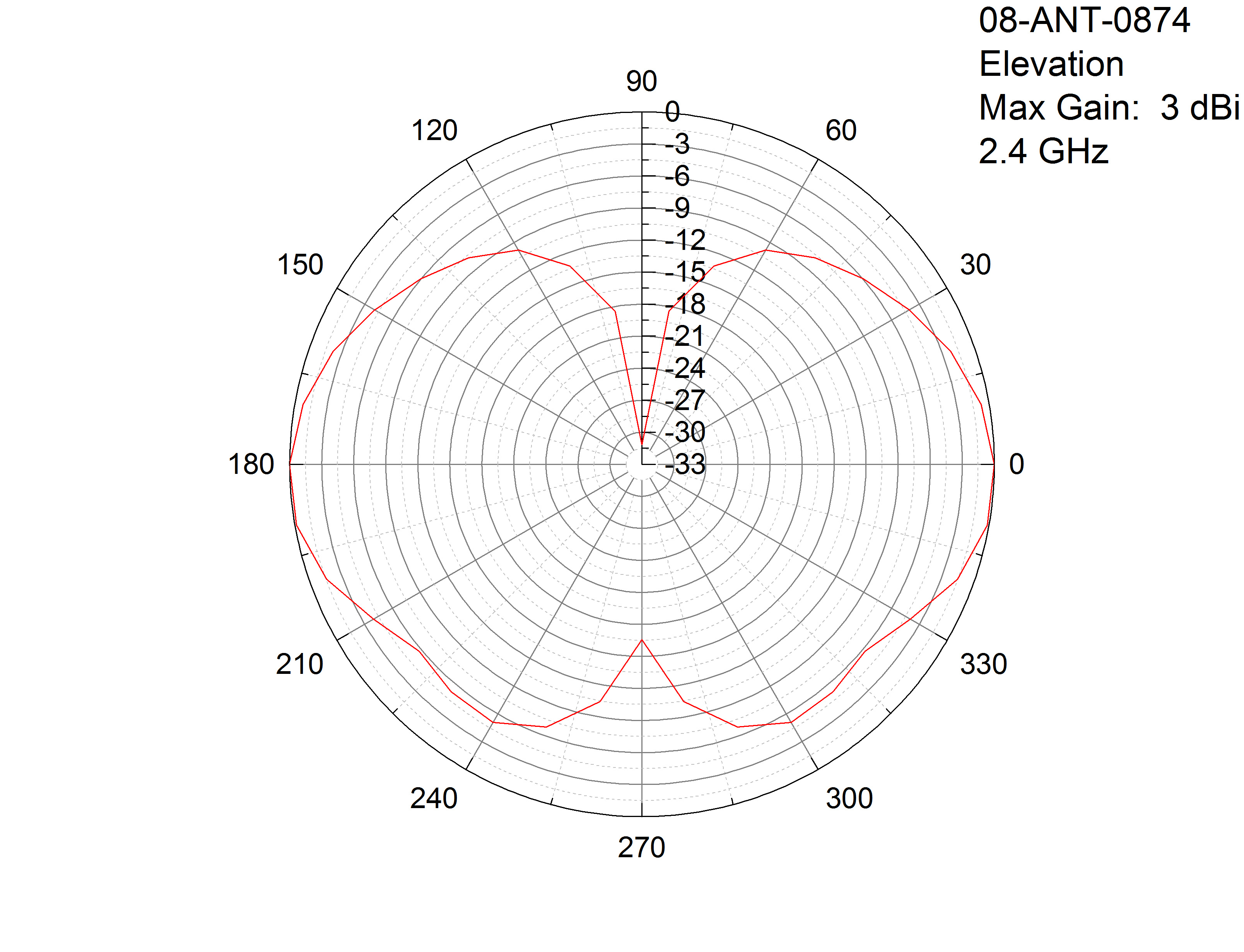
Antennas are the backbone of wireless communication, shaping and directing radio waves in specified patterns. An antenna pattern, or radiation pattern, is a graphical representation of the relative strength of the signal emitted or received by the antenna in different directions. Before calculating Rx Power, it’s crucial to understand these patterns, as they determine how well an antenna can receive signals from various directions, affecting the overall system performance.
Detailed Steps:
- Start by familiarizing yourself with antenna pattern diagrams, which typically include a main lobe, side lobes, and back lobes.
- Identify the gain of the antenna in the direction of interest, usually specified in dBi (decibels relative to an isotropic radiator) on the pattern diagram.
- Note that antenna patterns can be provided in both horizontal and vertical plots, and ensure you comprehend both when assessing overall coverage.
Summary:
Grasping antenna patterns aids in predicting and optimizing signal coverage. While technical in nature, understanding these patterns is foundational to calculating Rx Power. This knowledge allows an individual or business to strategically position antennas for maximum efficiency. However, interpretation may be complex for those unfamiliar with reading radiation diagrams.
Measuring Received Signal Strength
Received Signal Strength Indicator (RSSI) is a measure of the power present in a received radio signal. This numerical value aids in the computation of Rx Power and helps in assessing the performance of a wireless link.
Detailed Steps:
- Utilize a signal meter or software to measure RSSI at the receiver’s location.
- Record the RSSI value, which is often indicated in decibels milliwatts (dBm).
- Understand that while RSSI does not provide absolute power values, it serves as a comparative figure that can be related back to Rx Power readings.
Summary:
RSSI measurements offer a tangible starting point for Rx Power calculations. Accessible for non-technical users through various tools and applications, this step can empower better wireless network planning. However, RSSI may vary between devices, and understanding these variances is vital for accurate Rx Power computation.
Free-Space Path Loss
Understanding free-space path loss is essential when calculating Rx Power, as it describes the attenuation of the signal as it travels through free air without obstacles.
Detailed Steps:
- Identify the frequency of the transmitted signal.
- Calculate the distance between the transmitting and receiving antennas.
- Apply the free-space path loss formula to estimate signal attenuation.
Summary:
Acknowledging path loss influences allows for a more precise calculation of Rx Power and can guide adjustments in antenna positioning or power settings. The concept is straightforward, but actual conditions may vary due to environmental factors, introducing margin for error into calculations.
Link Budget Analysis
Link Budget is a comprehensive calculation that accounts for all gains and losses from the transmitter, through the medium, to the receiver. It is often used to determine the Rx Power at a given distance.
Detailed Steps:
- Gather all the necessary parameters: transmitter output power, gains and losses in the system, including those of antennas and cables, and the free-space path loss.
- Sum the gains and subtract the losses from the transmitted power to calculate the estimated Rx Power.
Summary:
Link budget analysis provides an all-encompassing approach to determine Rx Power, considering real-world factors. This technique necessitates a meticulous collection of data and some technical understanding but delivers a comprehensive view of system performance. The intricacy of the calculation might be a challenge for those new to the subject.
Antenna Gain and Directionality
The gain of an antenna illustrates its effectiveness in focusing energy in a particular direction compared to a theoretical isotropic antenna that radiates equally in all directions.
Detailed Steps:
- Identify the gain value from the antenna’s specifications or pattern diagram for the intended direction of reception.
- Incorporate this gain value into the Rx Power calculations to account for the directionality of the signal.
Summary:
Incorporating antenna gain into Rx Power estimates enhances the precision of wireless network planning. Although the concept may require some technical understanding, it is a testament to how antenna design influences communication effectiveness. High-gain antennas can vastly improve signal reception, but their increased directionality can also become a limitation when wide coverage is desired.
Cable and Connector Losses
Cables and connectors between the antenna and the receiver can introduce signal loss, known as attenuation, which should be accounted for when calculating Rx Power.
Detailed Steps:
- Determine the type and length of the cable used in the system.
- Research the specific loss (usually in dB per meter) associated with the cable type.
- Calculate the total loss introduced by the entire cable length and any connectors.
- Adjust the Rx Power calculation to reflect these losses accurately.
Summary:
Accounting for the loss induced by cables and connectors is key for accurate Rx Power determination, especially for longer cable runs or lower-quality connectors. This step is crucial, as overlooking it can lead to overestimating the Rx Power. The downside is the addition of complexity to the calculation, potentially intimidating for novices.
Polarization Mismatch Loss
Polarization refers to the orientation of the electromagnetic wave. If the transmitting and receiving antenna polarizations do not match, additional losses can occur which affect Rx Power.
Detailed Steps:
- Identify the polarization of both the transmitting and receiving antennas.
- Measure any misalignment angles between the two polarizations.
- Estimate the polarization mismatch loss based on these angles.
Summary:
Polarization mismatch loss consideration is vital for ensuring antenna alignment and maximal signal reception. This understanding can prevent potential setup errors, leading to a more reliable wireless communication system. However, grasping polarization concepts might be challenging for those without a technical background.
Antenna Orientation and Elevation
For directional antennas, both the horizontal and vertical orientation, as well as the elevation, are critical for maintaining optimal signal strength and thus affecting Rx Power.
Detailed Steps:
- Review the intended coverage area and the location of possible receivers.
- Align the directional antennas appropriately, considering both azimuth (horizontal direction) and elevation (vertical angle).
- Re-evaluate the antenna alignment periodically or when changes in the environment or desired coverage occur.
Summary:
Correctly orienting and elevating antennas is a practical step that significantly affects signal reception and Rx Power. While it requires some trial and error, this method can be highly beneficial for optimizing the coverage area with minimal technical expertise. Misalignment can lead to reduced performance, emphasizing the need for accuracy in these adjustments.
Environmental Factors and Interference
Environmental factors such as buildings, trees, and weather can cause signal degradation or reflection, while other electronic devices can create interference. Both have implications on Rx Power.
Detailed Steps:
- Perform a site survey to identify potential environmental obstacles and sources of interference.
- Adjust the wireless network setup to minimize these effects, such as changing antenna placement or frequency.
- Consider using specialized antennas or filters to combat interference.
Summary:
Acknowledging and mitigating environmental factors and interference is a proactive approach to ensuring optimal Rx Power levels. With careful observation and some practical changes, signal reception can be improved. However, predicting environmental impact often requires experience, and interference sources can be tough to track down.
Simulation Tools and Software
Simulation tools and software can model the antenna pattern and predict Rx Power levels throughout a given area, simplifying the complex calculations required.
Detailed Steps:
- Select a reputable simulation tool that is compatible with your system’s requirements.
- Input the necessary parameters such as antenna specifications, location, and environmental data.
- Use the software to simulate and analyze the anticipated Rx Power across the coverage area.
Summary:
Simulation software can save time and reduce errors in Rx Power calculations, providing a visual representation of the coverage area. This approach is particularly advantageous for those with limited technical prowess, allowing for easier system optimization. The main drawback may be the cost of obtaining and the learning curve associated with using sophisticated simulation tools.
Regular System Testing and Monitoring
Consistent testing and monitoring of the wireless network can validate Rx Power calculations and prompt adjustments when necessary.
Detailed Steps:
- Use tools like signal meters or network analyzers to gauge actual Rx Power at various points within the coverage area.
- Log results over time to track performance and identify trends.
- Make iterative adjustments to the wireless setup based on data collected to maintain optimal Rx Power.
Summary:
Regular testing is a critical ongoing process that helps align expectations with real-world performance, confirming the accuracy of calculated Rx Power. This hands-on approach can also lead to a deeper understanding of wireless systems. The challenge lies in the time and resources required for continuous monitoring.
In conclusion, calculating the received power from an antenna pattern involves a series of steps that, when taken together, can significantly enhance the performance and reliability of wireless communication systems. This understanding of the interplay between antenna characteristics, environmental factors, and technical parameters enables well-informed system design and optimization.
Frequently Asked Questions
Can I calculate Rx Power without specialized equipment?
While specialized equipment provides the most accurate measurements, some basic calculations can be made using antenna specifications and software tools. However, for practical field measurements, equipment like signal meters are generally required.
Does the antenna pattern affect the Rx Power calculation?
Yes, antenna patterns are essential to understanding where and how strongly the antenna radiates or receives signals, which directly impacts the Rx Power calculation.
How often should I re-calculate or measure the Rx Power?
It’s advisable to measure Rx Power whenever changes are made to the system or environment. Regular checks are also recommended to ensure optimal performance, especially if you suspect issues such as new sources of interference or changes in the physical surroundings.